
Call Support 24/7
+86-28-68724242

product
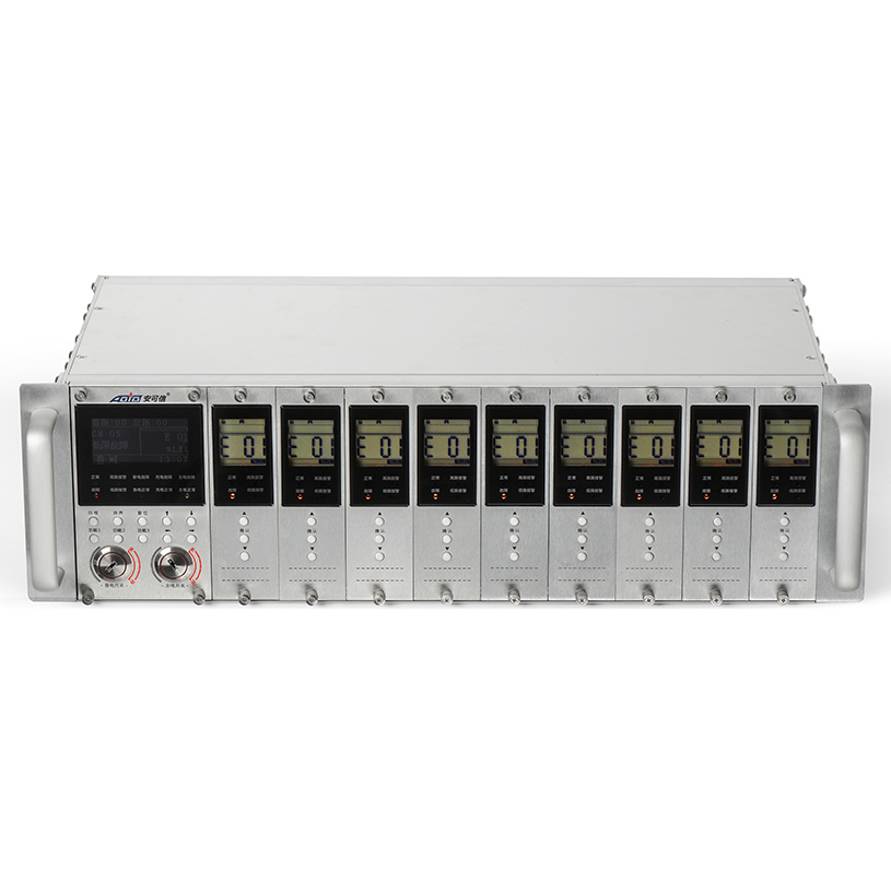

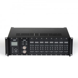
Gas Alarm Controller AEC2393a
Short Description:
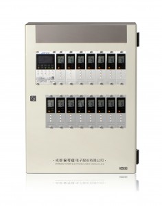
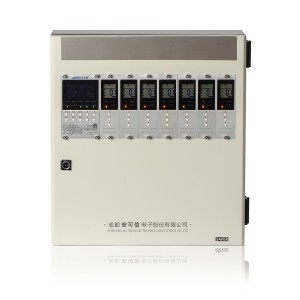
The 19” standard 3U panel-mounted all-metal rack has a slideway plug-in design in each channel; the standard 3U cabinet installation is characterized by easy installation, small volume (73% of AEC2392a) and anti-EMI/RFI interference;
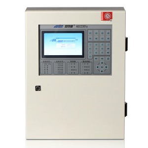
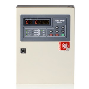
The master control card and channel cards are set separately but have a function of synchronous display. With a large LCD Chinese display screen, the master control card can realize Chinese menu operation as well as faster and easier display and operation;
Channel cards can work independently under an independent menu. Thus, failure of the master control card or failure of other channel cards will not have an impact on normal channel cards’ gas monitoring;
Channel cards can receive 4-20mA signal or switching value signal input and be connected with various devices, including combustible gas detectors, toxic and hazardous gas detectors, oxygen detectors, flame detectors, smoke/heat detectors and manual alarming buttones, etc.;
ACTION gas detectors are OEM & ODM supported and true mature devices, long-tested in millions of projects domestic and overseas since 1998! Don't hesitant to leave your any inquiry here!
Technical Specifications
|
Item |
Data |
|
Power supply card |
AC176V~AC264V (50Hz±1%) |
|
Standard configuration (10 circuits) |
one master control card, one power supply card, nine channel cards and one 19’’ standard 3U rack |
|
Boundary dimension of the standard rack |
19″ standard 3U rack (length x width x height: 483mm x 252mm x 132.5mm) |
| Configuration |
One master control card, nine channel cards and one 19’’ standard 3U rack |
|
|
Boundary dimension of the rack |
19″ standard 3U rack (length× width × height: 483mm×252mm×132.5mm) |
|
|
Item |
Master control card |
Channel card |
|
Operating power supply |
DC24V±6V |
|
|
Types of gas detected |
%LEL/%VOL/ppm |
|
|
Range |
(0~100)%LEL, (0~100)%VOL, (0~9999)ppm |
|
|
Value indication error |
±5%FS |
|
|
Operating mode |
Connected to channel cards or working independently |
Connected to the master control card or working independently |
|
Capacity |
10, to connect 9 channel cards; the master control card can connect one set of 4-20mA standard current signal |
One channel card connects one 4-20mA transmitter |
|
Power consumption |
3W |
1W/channel card |
|
Input signals |
Connect to (4~20)mA standard current signals or passive switching value signals locally or via a channel card |
4~20mA standard current signals or passive switching value signals |
|
Output signals |
1. RS485 bus communication signal (standard MODBUS protocol);2. Signals of 3 sets of relays (relays 1, 2 and 3); contact capacity: AC250V/10A or DC30V/10A. | One channel card can output:Signals of 3 sets of relays (high alarm, low alarm and failure); contact capacity: AC250V/10A or DC30V/10A |
|
Environmental condition for operating |
Temperature: 0℃~+40℃; relative humidity: ≤93%; atmospheric pressure: 86kPa~106kPa |
|
|
Alarming mode |
Audible alarm and LED visual alarm |
LED visual alarm |
|
Display mode |
OLCD Chinese display |
LCD segment code display |
|
Gross weight |
About 4.5kg (excluding standby power supply) |
|
|
Switch power supply |
AC176V~AC264V (50Hz±0.5Hz); under voltage test point 170V±10V; main power supply’s max. working current: 1A |
|
|
External standby power supply |
DC12V /7Ah×2 lead-acid battery (external case) |
|
| Mounting mode |
Standard 19” cabinet panel mounting |
|
Note: The default system input signals are (4~20)mA standard signals; when the input signal is a passive switching value signal, the default signal is a passive normally-open signal; if a user requires that the default signal should be a passive normally-close signal under such case, please specify when ordering.
Major Features
● The 19” standard 3U panel-mounted all-metal rack has a slideway plug-in design in each channel; the standard 3U cabinet installation is characterized by easy installation, small volume (73% of AEC2392a) and anti-EMI/RFI interference;
● The master control card and channel cards are set separately but have a function of synchronous display. With a large LCD Chinese display screen, the master control card can realize Chinese menu operation as well as faster and easier display and operation;
● Channel cards can work independently under an independent menu. Thus, failure of the master control card or failure of other channel cards will not have an impact on normal channel cards’ gas monitoring;
● Channel cards can receive 4-20mA signal or switching value signal input and be connected with various devices, including combustible gas detectors, toxic and hazardous gas detectors, oxygen detectors, flame detectors, smoke/heat detectors and manual alarming buttones, etc.;
● Channel cards’ multiple output types are applicable to linkage of on-site external control devices, good for integration of the host control system (e.g. DCS, PLC, etc.);
● The master control card integrates the functions of the power supply card and the one-circuit channel card. All channels can be equipped with a HART communication module, showing a strong function;
● Strong output driving capacity; each circuit’s output capacity is up to 8W, to drive the integrated detector of audible and visual alarms and display;
● The master control card integrates the functions of the power supply card of the former 292a and the one-circuit channel card. All channels can be equipped with a HART communication module, showing a strong function;
● Channel cards have a three-color backlight LCD, which can indicate normal, failure and alarming status clearly;
● With an OLED screen and an aluminum alloy wortle panel, this product looks beautiful and magnificent generally.
Control Panel
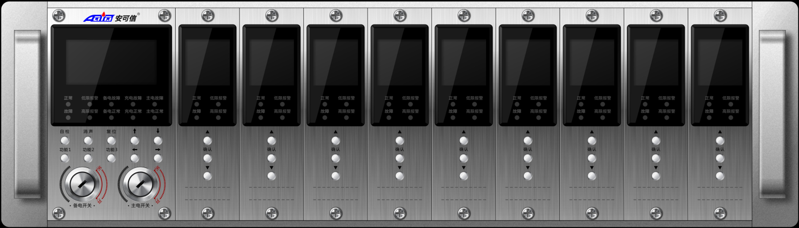
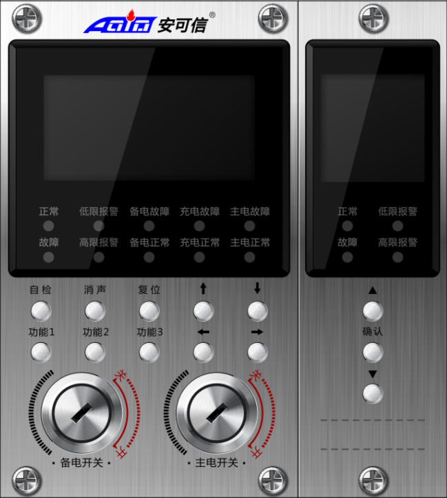
The gas control panel contains the display interfaces and operating interfaces of the master control card and channel cards, including the display screen, the LED status indicator, the alarm buzzer (installed inside the master control card) and operating keys. The master control card has ten operating keys while a channel card has three ones (see the following diagram):
External interface
The master control card connects 9 circuits of channel cards. Each channel card collects 4-20mA multi-line or passive switching value signal output communication equipment, such as GT-AEC2232bX, GQ-AEC2232bX, GT-AEC2232aT, AEC2338, GQ-AEC2232bX-P, AEC2338-D detectors and flame detectors. It can also connect other 4-20mA output transmitters. Two sets of built-in modules of the master control card can realize remote linkage of external devices (on-site sound and light, solenoid valves and fans, etc.). External devices (e.g. on-site sound and light) can also be controlled through three sets of relay signal output terminals provided by each channel card. Remote communication with the host system can be done through the RS485 communication interface so that the host system can monitor AEC2393a gas detection systems in several areas intensively.
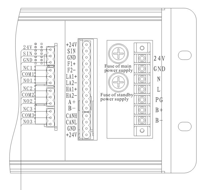
External interface
● Master control card:
F1+, F2-; LA1+, LA2-yyyyyyy; HA1+, HA2-: (3 sets) output terminals for relay external control signals output terminals
A+ and B-: RS485 communication interface connection terminals
L, PG and N: AC220V power supply terminals
B+ and B-: connection terminals of standby power supply
+24V, SIN and GND: input terminals for 4~20mA or passive switching value signals
● Channel card:
NC (normally closed), COM (Common) and NO (normally open): (3sets) output terminals for relay external control signals output terminals
24V, SIN and GND: input terminals for 4~20mA or passive switching value signals
When the signal connected is a passive switching value signal, the two ends of the signal are connected to 4~20mA (IN) and +24V. If DC24V power will be supplied to the equipment connected, the wiring is as shown in the system configuration diagram.
Internal terminal:
CAH, CAL, VSS and 24V: connection terminals for internal communication (connected in the factory)
Notes: (1) the maximum allowable wire diameter for connection terminals is 2.5mm2. (2) Factory default of the master control card’s relay output is passive switching value signal.